


Your shopping cart is currently empty.
Instructions & Tips
Installing Lights
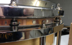
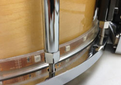
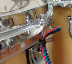
For snares, this is as simple as threading the lights through the drum hardware, as shown in the first couple of pictures. The upper and lower strips should be fed counter-clockwise around the d rum when viewed from above.
On the snare drums, the upper strip of lights will be a bit trickier to install than the lower strip because you’ll have to start feeding the strip directly behind the drum's mounting hardware. When the strip is installed correctly it will begin and end behind the carrier attachment. Install the lower strip the same way. When that is all done, the wires joining the upper and lower strips to the connector should be hanging to the left of the carrier attachment point.
You won't need any kind of adhesive for this, as the drum hardware does a good job of holding the lights in place. For some snare drums it may be necessary to loosen the upper head to make feeding the lights through easier.
Mounting Receiver
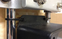
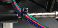
The receiver can be mounted to the snare using some small wire ties as shown here. The connector and power switch should be facing the left when viewed from behind the drum. Once the box is mounted, plug the lights into the matching connector on the box and you're done.
Installing Lights
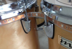
The single strip for a tenor can be fed behind the lugs in the same manner as the snare; the only difference is that you have to jump from drum to drum. This is best done near where the adjacent drums are closest together, as shown in the picture.
Tenor drums can be of different sizes, so you'll have to experiment to find the best starting and ending points for the tenor strip. Wherever your strip begins, it is a good idea to secure the wire (not the strip itself) with a small wire tie to prevent any accidental tugs on the wire from damaging the strip.
Mounting Receiver
There are many different tenor configurations, so you'll have to experiment to find the best location to mount the box. Velcro could attach the box to the shell of a drum, or wire ties or stretch cords could attach it to the frame. The tenor LED strips have a longer wire to allow for some flexibility in mounting options; just be sure to coil and wire-tie the excess once everything is in place.
Installing Lights
These are trickier, and will require adhesive to attach the strip to the inside of the hoop.
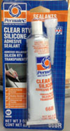
The casing enclosing the strips is silicone, and as such most adhesives won't stick to it very well, including all double-sided tape and most glues. What will reliably work on these strips is Permatex Clear RTV Silicone Adhesive, pictured here. It is available at auto parts and hardware stores.
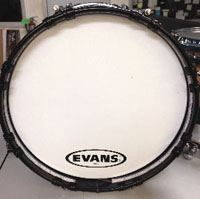
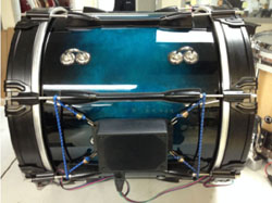
The strips should be placed so that their beginning and end points are evenly spaced around the very bottom of the drum as shown here in the middle picture.
The kit will include strips of different lengths for your different sized bass drums, so make sure you have the correct strip for each drum before attaching. As with the snares and tenors, using a small wire tie to prevent strain on the strips is a good idea.
Mounting Receivers
Stretch cords work quite well here, though Velcro remains an option. The box should be mounted below the carrier attachment points with the power button facing downward, as shown. Now that the lights are ready to go, it's time to fire up the system. Connect the included power supply for the control board to an AC outlet and plug it into the power jack on the back of the board, then switch it on. The board should start up. When it does, it will be in "blackout" mode, indicated by a flashing yellow light next to the blackout button. Press this button to turn off blackout mode.
How It Works
On the left side of the control board you’ll see twelve buttons labeled “scanners.” Each scanner corresponds to a single receiver or group of receivers, depending on your setup. If your system includes wireless flag poles, these will always be on scanner 1. The receiver boxes have a number on them denoting which scanner they will respond to. It is possible to select multiple scanners at one time, and all receivers assigned to the selected scanners will respond to control inputs.
For most systems, only the first three channels are used. The first controls red light output from the LEDs, and the second and third control green and blue. When one or more scanners are selected, moving the channel sliders will cause the corresponding receivers to change their light output.
Testing a Receiver Box
Switch on the box by pressing the power button. The red power indicator next to the button should illuminate. If the control board is powered on, then after a few seconds the box’s indicator should begin flashing to show that it is receiving a signal from the control board.
Now that the box is on and receiving a signal, select the scanner on the controller that matches the number on the receiver. The lights connected to the receiver should respond when channels 1, 2, and 3 are adjusted.
Testing a Flag Pole
Switch on the pole by pressing the power button in the bottom end. The power indicator on the visible circuit board should illuminate. If the control board is powered on, then after a few seconds the pole’s indicator should begin flashing to show that it is receiving a signal from the control board.
Now that the pole is on and receiving a signal, select scanner 1 on the control board. The pole should respond when channels 1, 2, and 3 are adjusted.
Programming a Sequence
The DMX-240A controller included with the system is a powerful tool that can store and play sequences and patterns. The user's manual for the controller contains instructions on how to use this and all other features, and can be found at the following address:
http://goo.gl/UGwqUR
Useful programming information can be found beginning on page 11.
All battery-powered components of this system must be cared for properly in order to ensure long life for the batteries.
- Never store the batteries while they are drained. They must be recharged prior to storage.
- Never leave a receiver box, wireless flag pole, or wireless control board on when not in use. If a device is left on while in storage, the battery can become completely drained and will quickly deteriorate.
- Never leave a device connected to the charger for a long period of time after it has finished charging. Once the light on the charger has gone from red to green, the device should be disconnected from the charger.
- Avoid storing the batteries in a hot environment for long periods of time. Never charge them in a hot environment.
- The wireless receiver boxes cannot be operated while connected to a charger, and will not power on when connected. After charging the battery and disconnecting the charger, check to make sure the receiver is off before storing.
- Wireless flag poles can be operated while connected to a charger, but this is not recommended as it interferes with the smart charging circuitry in the charger.
- While having lights on at full power is eye-catching, it is not necessary that they always be used at full brightness. Using a lower brightness for some scenes will save battery power and ensure a longer run time (especially for wireless flag poles and large bass drums) and makes brief periods of full brightness more dramatic.
- Like all battery powered systems, these will eventually run out of juice. Signs that a receiver box or wireless flag pole is low on power include reduced light output and loss of wireless signal.